Hull Design: From digital blueprints to waterborne reality
Designing a ship is an enormous undertaking where multi-million-dollar decisions must be made with near-perfect certainty long before any steel is cut. It is a blend of artistry and uncompromising physics. For over a century, naval architects have relied on the methodical practice of tank testing—towing a scaled model through a long basin of water—to predict a ship’s performance.
Today, this proven physical method works in powerful synergy with Computational Fluid Dynamics (CFD), a digital simulation technique that has revolutionized the early stages of design. This integrated approach, where digital optimization and physical validation go together, is the gold standard for creating efficient, safe, and comfortable vessels, from colossal cargo ships to elegant cruise liners.
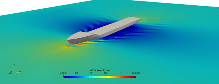
CFD
The Digital Sandbox: CFD for Initial Hull Optimization
The journey begins not with a physical model, but in the digital realm. Naval architects use CFD as a “digital sandbox” to rapidly test and refine ideas. This process creates a “digital twin” of the vessel, allowing designers to ask countless “what-if” questions without cost or delay. What happens if the ship is fully loaded versus in ballast? How does the water flow change if the vessel is trimmed slightly by the stern?
CFD provides the answers by solving complex fluid dynamics equations, simulating how water will flow around the virtual hull in any number of conditions. The key advantage is the sheer volume of insights gained at a low cost. Engineers can explore dozens of hull variations, visualizing complex phenomena like the vortices shedding from the stern or the precise flow of water into the propeller—details that are invisible to the naked eye in a physical test.
One of the most common CFD methods in naval architecture is RANS (Reynolds-Averaged Navier-Stokes), which provides a highly accurate, time-averaged prediction of forces and flow patterns. CFD’s true strength lies in its ability to provide a level of detail that is physically impossible to measure in a tank. For example, it can visualize complex fluid flow patterns and pressure fields, giving designers a precise understanding of where and why resistance is occurring. This is particularly transformative for optimizing features like the bulbous bow, a design feature that reduces wave-making resistance. In the past, optimizing a bulbous bow required countless physical iterations in a tank. With CFD, designers can now virtually test dozens of different bow geometries in a matter of hours, dramatically accelerating the design process and achieving a level of optimization that was previously unimaginable.
Tank Testing: The Definitive Reality Check
While CFD is a powerful design tool, it remains a simulation governed by mathematical approximations. The unforgiving laws of real-world physics demand empirical proof. To gain ultimate confidence, the design must be validated with a physical tank test—the definitive “reality check.”
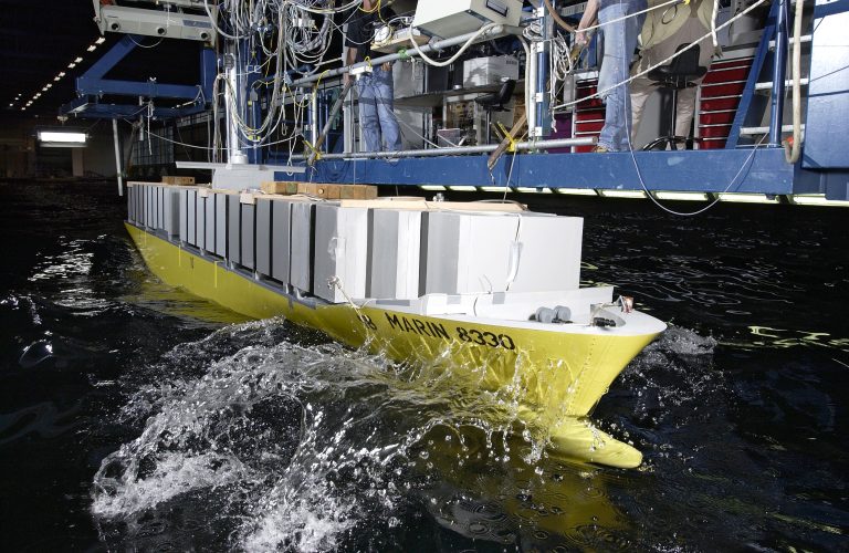
The enduring relevance of the tank test stems from its ability to provide real-world, measurable data on a scaled model. The need for this is rooted in the fact that a ship’s interaction with water is a complex interplay of forces that are difficult to predict with absolute certainty from design alone. A ship model basin is a controlled, man-made environment built to isolate and measure these forces. These are not small-scale experiments; a typical basin can be hundreds of meters long, with a precise towing carriage that acts as a mobile laboratory. The carriage tows a meticulously crafted model of the ship’s hull at carefully controlled speeds, while a suite of sensors records the forces acting on it. This physical data is the bedrock upon which all performance predictions are built.
The primary objective of these tests is to quantify resistance, the total force opposing the ship’s motion through the water. Resistance is not a monolithic force; it is composed of several key components that naval architects must understand to optimize a hull. The two most significant are:
– Frictional Resistance: This is caused by the viscosity of the water, a “stickiness” that creates drag against the hull’s surface. It’s a function of the hull’s wetted surface area and its smoothness.
– Wave-Making Resistance: As the ship displaces water, it creates a system of waves. The energy carried away by these waves is a form of resistance that becomes particularly dominant at higher speeds. The latter is particularly important, as the bow and stern waves can interfere with each other, either adding up to create a larger wave (and more drag) or partially cancelling each other out.
This is why a small change in hull length or shape can have a dramatic impact on a ship’s efficiency at its design speed. Tank tests allow engineers to measure these forces and, by extension, begin the critical process of predicting the power required for the full-scale vessel.
towing tank test
The Scaling Challenge: The Froude Number Explained
Measuring these forces on a model is one thing, but the true challenge is predicting them for the full-scale vessel. This is because the two forces don’t scale up in the same way. The industry’s solution, first developed by the pioneering work of William Froude, is to use a special scaling law known as the Froude Number (Fr=V/√gL).
Imagine throwing a rock into a pond and watching the ripples it creates. Now, imagine a smaller rock thrown at a different speed. To get the same pattern of ripples, you can’t just scale down the speed in the same way you scaled down the size. Similarly, a ship’s wave-making resistance is governed by a special ratio that connects speed and length. The Froude Number is a dimensionless value that compares inertial forces with gravitational forces. To get an accurate prediction of wave-making resistance, engineers run the model at a speed that matches the Froude Number of the full-scale ship.
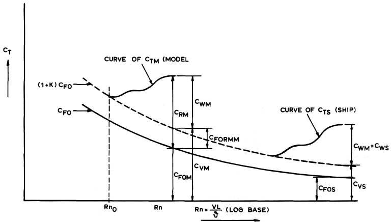
On the other hand, frictional resistance is governed by the Reynolds Number (Re=VL/ν), which compares inertial forces with viscous forces. It’s physically impossible to match both the Froude and Reynolds numbers at the same time. The industry’s solution, standardized by the International Towing Tank Conference (ITTC), is to run the test by matching the Froude number to accurately capture the wave patterns. The wave-making resistance is then scaled up directly, while the frictional component is calculated using proven empirical formulas for both the model and the ship. This blended method provides a highly reliable prediction of the full-scale ship’s resistance.
Beyond the Hull: Appendages and Hull Geometry
A ship is more than just its hull. Appendages—like the bulbous bow, rudder, bilge keels, propeller shaft brackets, and openings for thrusters—all contribute to the overall resistance and performance. A towing tank allows engineers to precisely measure the impact of each of these components.
For example, a bulbous bow is not a simple sphere; its specific shape must be fine-tuned to create a wave that interferes destructively with the ship’s own bow wave at its optimal speed, significantly reducing wave-making resistance. Similarly, the openings for bow thrusters, used for maneuvering, and the tubes enclosing propeller shafts (known as propeller tubes or stern tubes) must be carefully designed to minimize turbulence and drag while still performing their intended function. The testing process involves measuring the resistance with and without these features to isolate and quantify their individual effects on the total drag.
A key factor in a ship’s resistance is its hull shape, and naval architects use several coefficients to define this. The Block Coefficient (CB) is one of the most important. It’s a measure of the “fullness” of the hull and is calculated as CB=V/(L×B×T), where V is the volume of the hull below the waterline, L is the length, B is the breadth (width), and T is the draft (depth). A low block coefficient (e.g., CB = 0.5) indicates a very slender, streamlined hull, while a high block coefficient (e.g., CB = 0.8) indicates a full, box-like hull, typical of a bulk carrier, designed to maximize cargo volume at the expense of higher resistance.
Another important measure is the Midship Section Coefficient (CM), which compares the area of the largest underwater cross-section of the hull to the surrounding rectangle. A high CM means a very full, U-shaped hull, while a lower CM means a V-shaped hull. Understanding these coefficients allows naval architects to design the optimal hull shape for a vessel’s intended purpose.
Extrapolation of model results to ship using the form factor method
From Resistance to Power: The Efficiency Chain
The goal of a tank test is not just to measure resistance, but to use that data to select a propulsion system and predict a ship’s final performance. This process moves from the “effective power” of the hull to the “brake power” of the engine, following a series of efficiency losses known as the efficiency chain.
The first step is to determine the effective power (PE), which is the power required to overcome the total resistance of the hull. This is the ultimate benchmark for the hydrodynamic efficiency of the hull form. The next step, however, is to account for the inefficiencies of the propulsion system itself. Tank tests with a spinning propeller measure the interaction between the propeller and the hull’s wake, allowing engineers to calculate the propulsive efficiency. This efficiency is a complex factor that accounts for the propeller’s performance, the turbulent wake of the hull, and the thrust deduction caused by the propeller’s action.
The result of this stage is the delivered power (PD), which is the power required to be delivered to the propeller shaft. By further accounting for the efficiency of the gearbox and shafting (shaft efficiency), naval architects can finally arrive at the brake power (PB)—the actual power the engine must produce to move the ship at its intended speed. This detailed breakdown, from the effective power of the hull to the brake power of the engine, is a critical output of the tank test, providing the necessary data to specify the vessel’s propulsion system and estimate its operational costs.
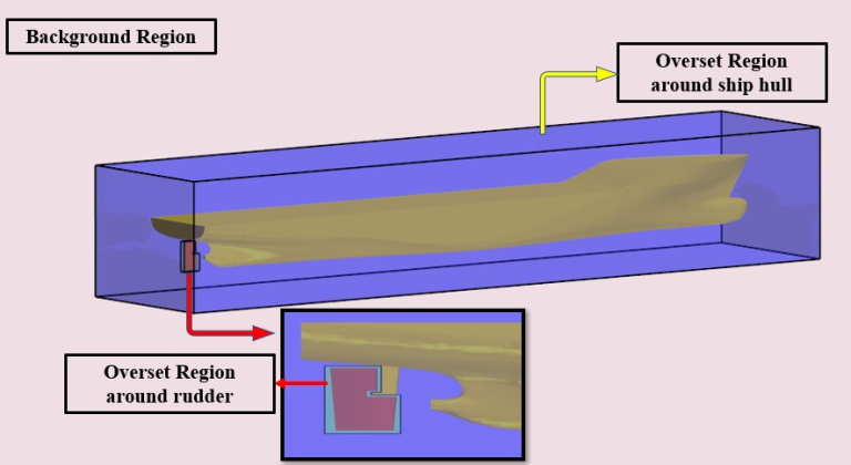
Background Region
The Synergy of Physical and Digital: Tailoring the Process
The modern ship design process is a seamless integration of tank testing and CFD, with the specific emphasis of this collaboration changing depending on the type of vessel being designed.
For Cruise Ships, the focus is heavily on passenger comfort, stability, and maneuverability. Tank testing is crucial for detailed seakeeping tests, which use wave generators to simulate rough seas and meticulously measure motions like pitching and rolling. CFD complements this by helping to design and optimize stabilizing fins and thruster systems. The hull form, while still optimized for efficiency, is also tailored to minimize motions at a specific, constant cruising speed.
For Cargo Ships, the paramount concerns are efficiency, capacity, and structural integrity. Their operational speeds are generally lower than cruise ships, making frictional resistance a larger proportion of the total drag. Both tank testing and CFD are used to meticulously optimize the hull for minimal resistance and maximum efficiency, often at multiple loading conditions to account for the ship being both full and empty. Seakeeping tests for these vessels focus more on preventing structural damage and ensuring the safe transport of cargo in extreme weather, with less emphasis on passenger comfort.
In the final, modern design process, CFD is the workhorse for early-stage design exploration, allowing naval architects to rapidly identify the most promising hull forms. Once a few key designs have been selected, they are then built as physical models for tank testing. This final tank test serves as a critical validation of the CFD results, providing an empirical check on the theoretical assumptions and computational models. While CFD and tank tests are often in very close agreement (typically within 1-3%), the tank test offers the undeniable authority of a physical experiment. This powerful synergy, where CFD handles the rapid iteration and optimization and tank testing provides the definitive verification, ensures that the final vessel is not only optimized for performance and efficiency but is also backed by the highest standards of engineering validation.
Don’t miss news, updates, and reviews of the world of cruises on Cruising Journal, with photos, videos, and cruise deals.


